
View Basket0 item(s) in the basket.
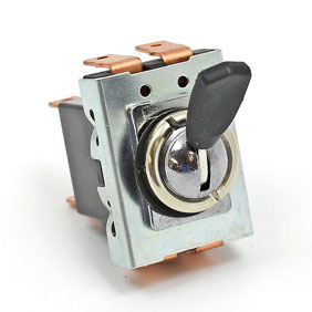
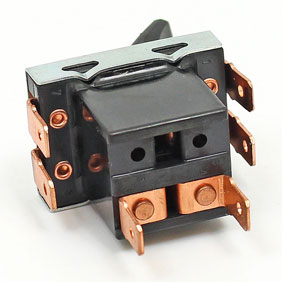
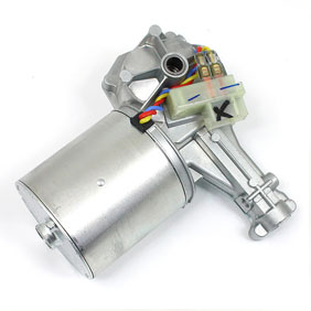
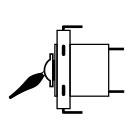
This is a popular combination, used on MGs, Triumphs, Land Rovers and Morgans. It is also popular with kit and special builders and as an upgrade modification for older vehicles. This combination of the 35927 switch with the LRW110 motor gives 2 wiper speeds with a self-park function. Not too difficult to wire from scratch, but can still confuse. Note that your wiring will probably be different colours, so it would be worth re-drawing to suit.
If it is a first electrical project then take your time to understand the circuits. Use over-length loose wires with the quick crimp connectors and get it fully working before trying to incorporate it into the loom neatly. Replace the quick crimp connectors with the quality double crimp types with insulating boots. The care taken here will largely determine how reliable the circuit is.
This is the basic circuit, it is recommended to add relays to the circuit to reduce power drops and protect the switch.
Postion these near to the wiper motor.
Some people recommend adding an earth wire to the wiper motor body, but this shouldn’t be needed. Remember to always have fuse protection
Notes
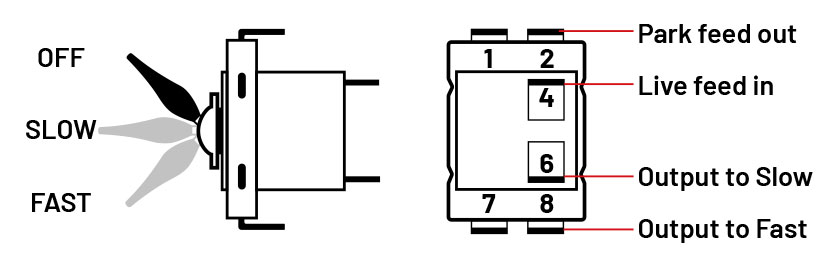
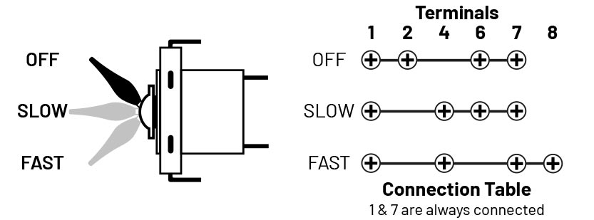
Switch terminals 1 and 7 are always linked, regardless of switch position and are not used in this application.
Switch terminal 4 is power feed to the switch, controlled by the ignition switch (a fused accessories circuit)
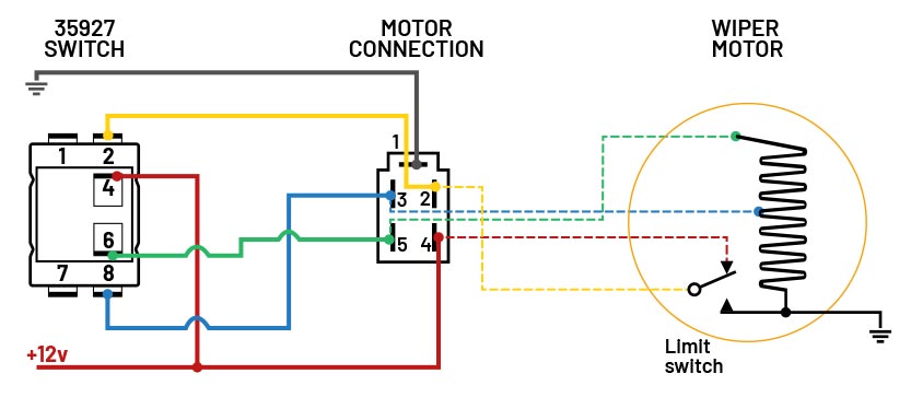
Note - colours are only illustrative, yours will be different
Diagram shows limit switch connected - wiper arms not yet parked
OFF (switch off, wiper arms not yet parked)
Switch terminals connected 1 - 2 - 6 - 7
No direct power to 8 (Fast) or 6 (Slow)
Park function (2 on switch) is supplied power via the limit switch (yellow wire). This is connected to Slow (6 on switch)
Power supplied by green wire, motor runs until limit switch is tripped to off.
OFF (switch off, wiper arms are parked)
Switch terminals connected 1 - 2 - 6 - 7
No direct power to 8 (Fast) or 6 (Slow)
Limit switch NOT supplying power
Motor at stop
SLOW
Switch terminals connected 1 - 4 - 6 - 7
Power from 4 at switch is connected to 6 (Slow)
Green wire supplies power to resistor/coil in motor
Motor runs slow
FAST
Switch terminals connected 1 - 4 - 7 - 8
Power from 4 at switch is connected to 8 at switch (Fast)
Blue wire supplies power to connection 3 at motor
Motor runs fast
Related Spare Parts
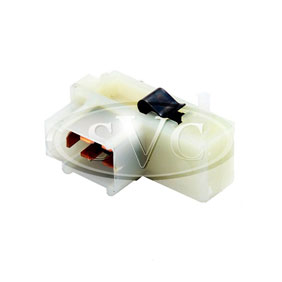
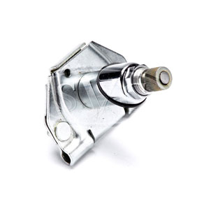
Replacement park switch (Limit Switch) and connection block for 14w wiper motor
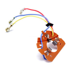
Replacement brush and pad set for 14w wiper motor - repair & restore.
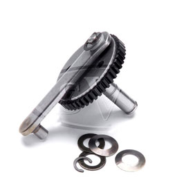
Drive gear, from 90º to 130º sweep. Available in 5 degree increments.
Wiper wheel boxes for the Lucas type 14w wiper motor

Rubber mounding pad and strap to reduce body noise
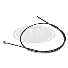
Drive rack, supplied as a 1.5 metre length
Please note
All articles and guides are provided only for the interest of classic and vintage car owners. A certain level of mechanical and electrical knowledge will be required in undertaking work as described in these articles, and anyone unsure of their abilities is advised to seek professional assistance. Electrical faults can cause fires.
SVC (Vintage Supplies Ltd) cannot be held responsible for any breakages and injuries that may occur, while working on a vehicle following any guides provided. With older vehicles being exempt from MOT checks, responsibility for vehicle safety and legality rests entirely with the owner.